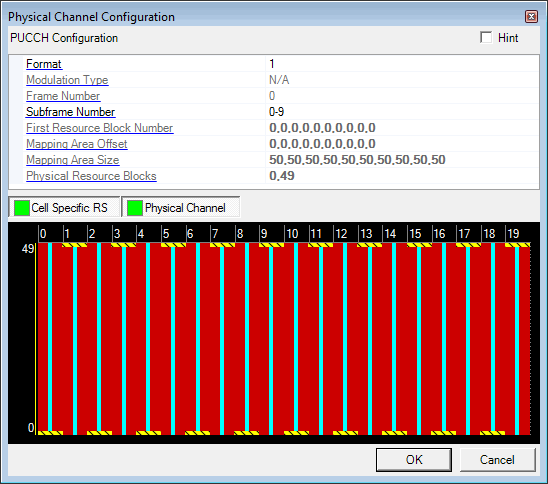
 in the Physical Channel node and select PUCCH to open the Configure PUCCH
window. The following figure shows the Configure PUCCH window with the
default settings.
in the Physical Channel node and select PUCCH to open the Configure PUCCH
window. The following figure shows the Configure PUCCH window with the
default settings.Before adding a PUCCH channel as described below, delete any existing transport channel, physical channel, or resource block group that occupies the resource blocks that your new PUCCH channel will occupy. If you add a new PUCCH channel without first deleting a conflicting channel or resource block group, a "code conflicted" error occurs when you generate the waveform.
Click the Add Channel button
 in the Physical Channel node and select PUCCH to open the Configure PUCCH
window. The following figure shows the Configure PUCCH window with the
default settings.

Choice: 1 | 1a | 1b | 2 | 2a | 2b | 3 | 1 Short | 1a Short | 1b Short | 3 Short
Default: 1
Select a format for the PUCCH from the drop-down list. The modulation type and number of Mbits per subframe for each format are shown in the following table. See 3GPP TS 36.211 for more information.
|
PUCCH Format |
Modulation |
Number of Mbits per Subframe |
|---|---|---|
|
1 and 1 Short |
n/a |
n/a |
|
1a and 1a Short |
BPSK |
1 |
|
1b and 1b Short |
QPSK |
2 |
|
2 |
QPSK |
20* |
|
2a |
QPSK + BPSK |
21* |
|
2b |
QPSK + QPSK |
22 |
| 3 and 3 Short | QPSK | 48 |
*Applicable for Normal cyclic prefix only.
See 3GPP TS 36.211, 36.212 and 36.213 for more information.
Displays the modulation type for the PUCCH for the selected format as shown in the table above.
See 3GPP TS 36.211, 36.212 and 36.213 for more information.
Displays the frame number (0) for the PUCCH.
Range: 0 to 9
Default: 0–9
Enter a subframe number for the PUCCH to occupy.
Range: 0 to (Maximum resource block size – 1)
Default: 0
0 = The PUCCH occupies the lowest numbered resource block in the defined mapping area in the first slot of the subframe and the highest numbered resource block in the defined mapping area in the second slot of the subframe.
1 = Moves the PUCCH in slot 1 of the subframe to the next highest numbered resource block; moves the PUCCH in slot 2 of the subframe to the next lowest numbered resource block (relative to the 0 setting).
2 = Moves the PUCCH in slot 1 of the subframe up two resource blocks; moves the PUCCH in slot 2 of the subframe down two resource blocks (relative to the 0 setting).
The Resource Mapping Graph at the bottom of the window displays your setting.
Range: 0 to (Maximum resource block size – 2)
Default: 0
The integer you enter here defines the number of resource blocks that the mapping area is offset from resource block 0.
Range: 1 to the number of resource blocks in the selected System Bandwidth
The value you enter here defines the number of resource blocks in the PUCCH mapping area. The thin yellow line to the left of the resource mapping graph shows the size of the mapping area.
Displays the numbers of the resource blocks occupied by the PUCCH, separated by a comma. If you change the mapping area size, mapping area offset, or first resource block number, the resource block numbers are updated accordingly when you click in this cell.